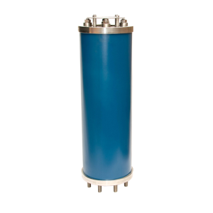
Description
Variant Combination Air Release and Vacuum Break (Sewerage)
LARGE ORIFICE AIR DISCHARGE
During initial filling, the pipeline is filled with air. As water is introduced into the pipeline, the air flows naturally towards the highest points along the pipeline. Air valves, positioned at these high points, allow air to pass freely through the large orifice to the atmosphere.
VACUUM BREAK
During scouring or when a pipeline ruptures, it is imperative that the pipeline is protected from damaging negative pressures. Variant air valves provide a full bore, unimpeded flow path that maximizes the valve’s air intake capacity. The rapid inflow of air effectively prevents damaging vacuum conditions.
PRESSURIZED AIR RELEASE
During normal operating conditions, air accumulates in the air valves, located at the high points along the pipeline. Once sufficient air has collected in the valve, the automatic float drops, opening the automatic orifice and allowing the air to escape to the atmosphere.
SURGE PROTECTION
Should pump stoppages cause water column separation within the pipeline, the air is admitted rapidly through the air valve’s large orifice to protect the pipeline. As the water column returns, this air is then gradually discharged through the air valve’s anti-shock orifice. By restricting the discharge through the anti-shock orifice, sufficient air is retained in the pipeline to create a temporary surge accumulator. In instances where pipelines are filled too quickly, the anti-shock mechanism is blown shut by the excessive airflow. Air is now only released through the anti-shock orifice in a controlled manner, creating an air cushion in the pipeline. This air cushion slows down the approaching water column and absorbs any potential surges.
FEATURES
- Optimum flow characteristics
- Low-pressure sealing
- Compact design
- No dissimilar metal corrosion
FUNCTIONS
- High capacity air discharge
- High capacity air intake
- Pressurized air release
Surge alleviation
AIR VALVE SELECTION AND TECHNICAL SPECIFICATIONS
SIZING
The overriding criteria for air valve sizing is the intake requirement under vacuum conditions. To protect the pipeline and joints, it is necessary to limit the system negative pressure to 3.5m vacuum by admitting sufficient air into the pipeline as it empties. One needs to consider the pipeline diameter, gradient, rupture percentage and scour valve size when calculating the required flow rate. Once the required intake flow rates have been calculated, the appropriate air valve can be selected.
Although the air valve size is determined by the air flow required under the vacuum conditions, the flow rate (switching rate) at which the anti-shock mechanism is activated, needs to be considered to ensure that your pipeline will be adequately protected.
INTAKE FLOW RATES AT 3 .5 METERS VACUUM
| VALVE SIZE MM | MODEL LS |
|---|---|
| 50mm | 208 L/S |
| 80mm | 558 L/S |
| 100mm | 772 L/S |
| 150mm | 2012 L/S |
| 200mm | 3294 L/S |
ORIFICE SIZES AND SWITCHING RATES
| SIZE MM | 50mm LS | 80mm LS | 100mm LS | 150mm LS | 200mm LS |
|---|---|---|---|---|---|
| Anti-shock orifice | 9 | 14 | 17 | 25 | 34 |
| Inlet | 50 | 80 | 100 | 150 | 200 |
| Outlet | 50 | 0 | 100 | 150 | 200 |
| Switching Flow L/S | 30 | 119 | 161 | 447 | 632 |
MODEL LS SPECIFICATIONS
| NOMINAL SIZE | MODEL NUMBER | PRESSURE RATING | HEIGHT | DIAMETER |
|---|---|---|---|---|
| 50mm Flanged | 050LS16 | 1600KPA | 650mm | 175mm |
| 50mm Flanged | 050LS25 | 2500KPA | 650mm | 175mm |
| 80mm Flanged | 080LS16 | 1600KPA | 660mm | 200mm |
| 80mm Flanged | 080LS25 | 2500KPA | 660mm | 200mm |
| 100mm Flanged | 100LS16 | 1600KPA | 666mm | 235mm |
| 100mm Flanged | 100LS25 | 2500KPA | 666mm | 235mm |
| 150mm Flanged | 150LS16 | 1600KPA | 767mm | 285mm |
| 150mm Flanged | 150LS25 | 2500KPA | 767mm | 300mm |
| 200mm Flanged | 200LS16 | 1600KPA | 850mm | 340mm |
| 200mm Flanged | 200LS25 | 2500KPA | 850mm | 360mm |
Working temperatures: 4 – 75 Degrees Celcius.
Standard factory tests Hydrostatic – 1.5 times working pressure.
WORKING TEMPERATURES
- 4 – 75 Degrees Celcius.
STANDARD FACTORY TESTS:
- Hydrostatic – 1.5 times working pressure.
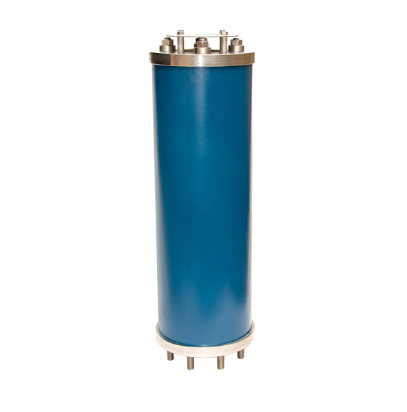
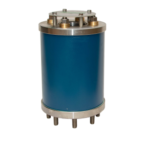
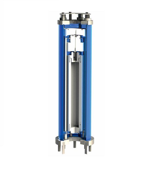
TYPE
Triple acting three stage
MATERIAL SPECIFICATION
BODY : 304/316 Stainless steel
AUTOMATIC FLOAT : High Density polyethylene
KINETIC FLOAT : High Density polyethylene
ANTI SHOCK FLOAT : High Density polyethylene
AUTOMATIC SEAL : EPDM
KINETIC SEAL AND O RINGS : Nitrile
SPACERS, STUDS, NUTS AND BOLTS : 304/316 Stainless steel